What you’ll need:
- A micro:bit, battery pack and micro USB cable, plus a suitable computer for programming.
- 1 small servo motor (eg a SG90 3,3v servo)
- 3 crocodile clip leads.
- 3 breadboard jumper wires.
Step One: The Basic Code
You’re going to use the Python editor on the micro:bit website for this jam.
Click here to open the editor.
Copy the Python script below to the editor:
# http://python.microbit.org/editor.html


from microbit import *

display.show(Image.TARGET)

# 3 LED

while True:

    pin0.write_digital(0)
    sleep(500)
    pin1.write_digital(0)
    sleep(500)
    pin2.write_digital(0)

    sleep(5000)

    pin0.write_digital(1)
    sleep(500)
    pin1.write_digital(1)
    sleep(500)
    pin2.write_digital(1)

    sleep(5000)
When you’re done, download the .hex file and flash it to your micro:bit. Remember to give the script a memorable name!
Step Two: The Components
Lets take a look at the LED. It has to be connected the right way round.
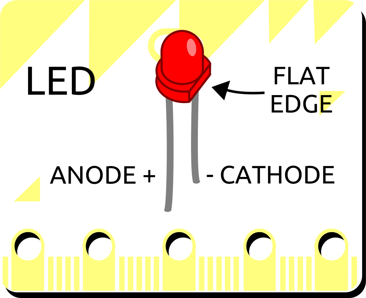
Note that there’s a long leg and a wee short leg. The long leg (anode) connects to the positive side. The short leg (cathode) connects to the negative, or Ground side.
Oh, and you’ll notice that there’s a small flat edge at the base of the LED. This also helps indicate the cathode. Connecting the LED to the power backwards is very likely to cause a puff of smoke to escape and your LED to mysteriously stop working…
Step Three: Wiring Up the Project
First things first make sure your micro:bit is powered down.
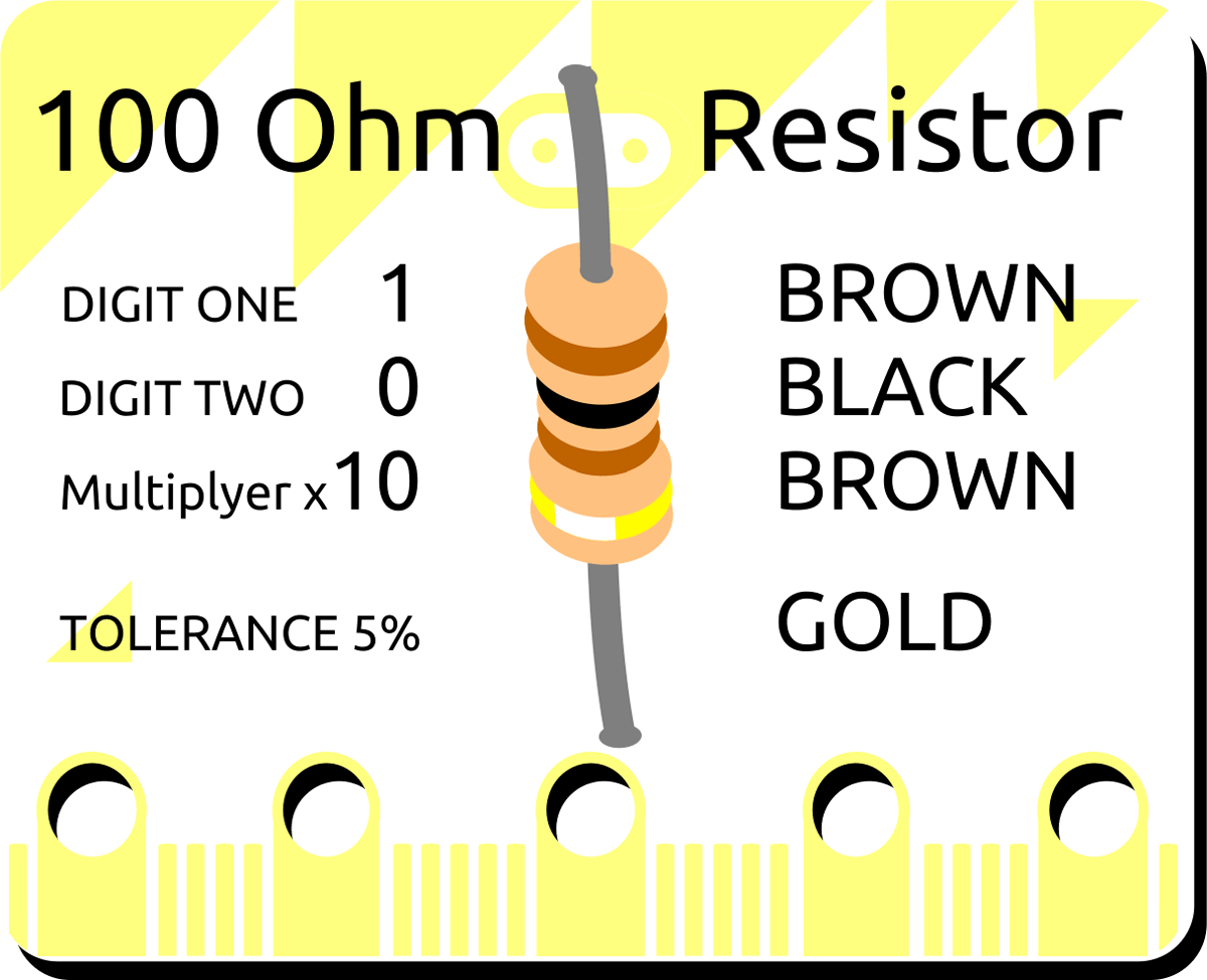
Use the crocodile clips to connect the short (negative) leg of the LED to one end of a 100 ohm resistor (it doesn’t matter what end). Connect the other end of the resistor to GND on the micro:bit.
Lastly, connect the long leg of the LED to Pin 0 on the micro:bit. With the circuit complete, current will flow from Pin 0 to GND through the LED you’ve connected.
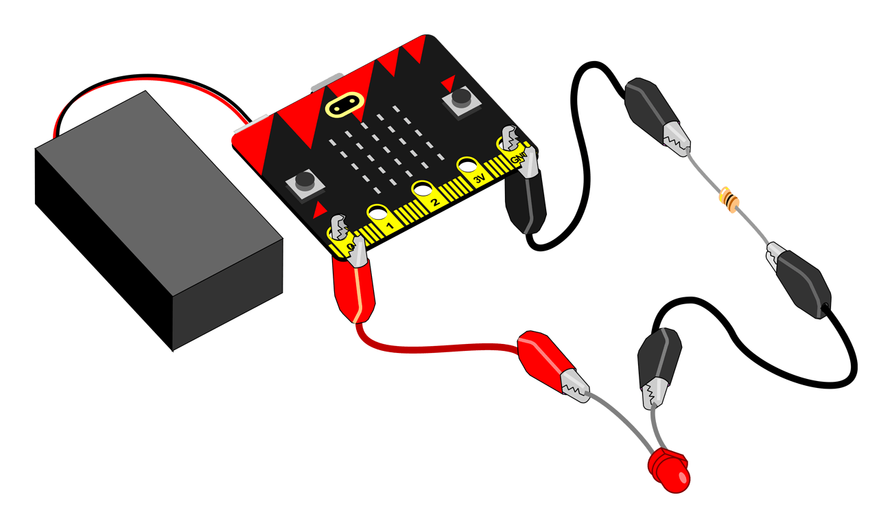
Now you’ve connected all of your components, it’s time to test if it’s all wired up and coded correctly! Power on your micro:bit and, all being well, your LED should be blinking on and off.
Our creepy robot doll in this project has two eyes – can you connect an additional LED to Pin 1 or 2?
Now’s a great time to tinker with the code to make it more interesting. See if you can make the LEDs blink faster, or opposite to each other.
On, off. On, off… all a bit digital, isn’t it? How about a nice pulsing and fading LED? We can generate a more analogue effect using “pulse width modulation” It’s still just turning the LED on and off but it’s so fast it looks like the brightness is changing.
Step Four: A More Advanced Code
If you want to create a pulsing LED effect, disconnect the LEDs and connect your micro:bit to your computer again.
Open the Python editor again and replace the script you’ve previously written with the one below:
# http://python.microbit.org/editor.html
# single pulsing LED

from microbit import *
pin0.write_digital(0)

sleep(5000)

while True:

    for i in range(0,128,1):
        pin0.write_analog(i)
        sleep(10)

    for i in range(128,0,-1):
        pin0.write_analog(i)
        sleep(10)
Download the .hex file and update your micro:bit.
Step Five: It’s Just Step Three Again
Reconnect the LED to Pin 0 as before and power on your micro:bit Hopefully you now have a gently pulsing LED. When you’re confident how this new script works, tinker with the code some more to really make it your own.